Seeing in 3D
Between the BearID project and Kaggle competitions, most of our efforts have been focused on 2-dimensional images. In fact, most of the deep learning advancements in visual perception are based on 2D image sets such as ImageNet. But the real world is 3-dimensional. How can machines perceive the world in 3D?
Before we start to think about machine learning in 3D, let us first understand how we can sense the world in 3D. We know that one of the most common sensors we use for 2D sensing is the digital camera. What are the options for 3D image sensing? It turns out there are quite a few.
3D Imaging Technologies
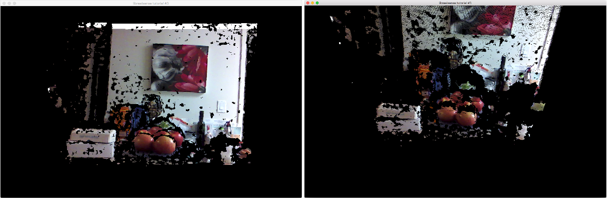
The idea with 3D imaging is to figure out where everything is in 3D space. To figure out where every point of every object is in 3D has a lot of challenges. Instead, these 3D technologies sample a subset of points in the scene, determining their X/Y/Z coordinates, creating a point cloud. The image below shows a point cloud from 2 different perspectives.
The following sections describe various 3D imaging technologies.
Photogrammetry
Photogrammetry is the use of photography to make measurements. Photogrammetry has many applications, one of which is generating 3D structure from multiple 2D images. The method involves photographing a scene from multiple, overlapping angles. By applying concepts from optics and geometry, points from overlapping images can be correlated and their location in 3D space can be calculated (see image from the paper Reconstructing Rome below).
These calculations can be used to create a point cloud of the scene, but only if there are a sufficient number of images with sufficient overlap. Since this method produces a 3D structure using photos from various locations, it is also known as Structure from Motion (SfM). For an interesting example of SfM, check out Building Rome in a Day, where a research team from the University of Washington reconstructed 3D models of Rome (and a few other cities) using photos harvested from Flickr.
Pros: Can use any digital cameras; no light projection
Cons: Requires a lot of photos with lots of overlap; needs a lot of compute
Stereo Camera
A stereo camera utilizes two image sensors fixed at a known distance and orientation to emulate binocular vision. This is a special case of photogrammetry called stereophotogrammetry. The stereo setup can be used to calculate a depth map using triangulation.
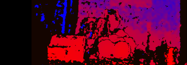
A depth map is a 2D representation of the 3D information. Each pixel in the depth map represents the distance of the corresponding object from the camera. Here’s an example depth map image, where the redder areas are nearer and the bluer areas are father.
The depth information can be combined with the RGB data to calculate a point cloud of the scene. The calculations for a stereo camera are similar to photogrammetry, but the relationship between the two cameras is known, requiring less computation.
An example of stereo camera is the ZED from Stereolabs.

Pros: Fairly small; no light projection
Cons: Still needs a lot of compute; depth perception limitations when cameras are close to each other
Structured Light Camera
Structured light utilizes a projected pattern of light to augment the scene. Patterns can range from lines and grids to random dot patterns. The camera senses the scene and calculates the depth information based on the deformation of the known pattern. To avoid disrupting the scene, the projected light pattern is often something outside the visible spectrum, such as infrared (IR).
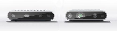
Some good examples using of a structured light are the latest Intel RealSense cameras, D415 and D435 (pictured above). They actually combine structured light and stereo (Structure+Stereo) by utilizing an IR projection and two IR image sensors to provide more accurate depth information. The depth map is combined with a color camera to produce point clouds.
Pros: Fairly small; easier computation; Structure+Stereo has better resolution and accuracy compared to Structured or Stereo alone
Cons: Requires projected light
LiDAR
LiDAR determines the distance to a target by projecting a laser and measuring the time it takes to receive the reflection. By scanning the laser across a scene, a point cloud can be generated, however the point cloud does not provide color information. These laser scanning LiDAR are used quite extensively in autonomous cars. The image below shows a Google Car and LiDAR image from an article in Popular Science. The rings indicate the scanning pattern of the laser.
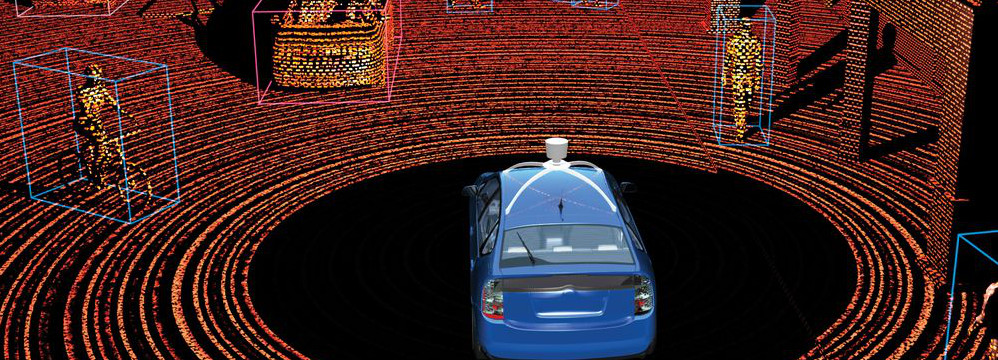
Pros: High accuracy and good scene coverage with scanning LiDAR; little computation required
Cons: No color; fairly large and heavy; quite expensive; requires projected light
Time of Flight (ToF) Camera
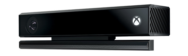
Similar to LiDAR, a Time of Flight (ToF) Camera also determines distance by measuring the “time of flight” of light. Rather than scanning a single laser across a scene, the ToF camera projects a broad beam and captures the entire scene at once. The sensors are arranged in a grid, much like image sensors, and distance is measured on a pixel by pixel basis. There are a number of projection/sensing technologies including phase detection, range gated imagers and direct ToF imagers. ToF camera technology is sometimes referred to as scannerless LiDAR or Flash LiDAR.
A popular example of a ToF camera is the Kinect for Xbox One (the original Kinect for Xbox 360 was a structured light camera):
Pros: Fairly small; little computation required
Cons: Limited resolution; requires projected light; fairly new (so still a bit pricey)
Comparison
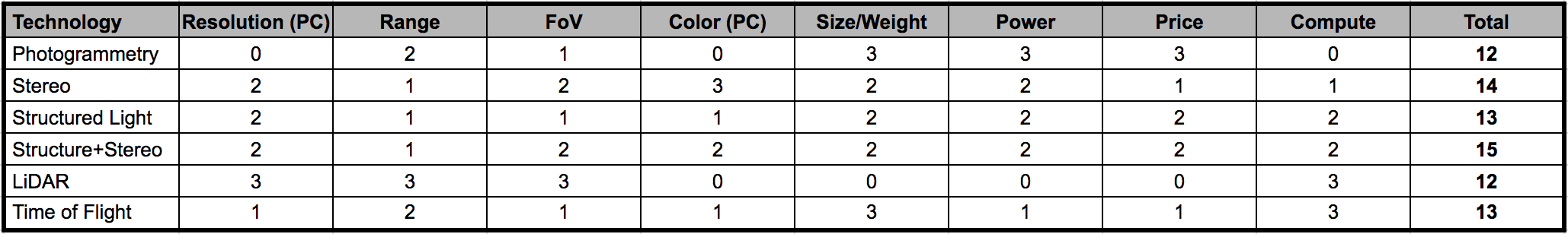
We wanted to start experimenting with 3D sensing, so we compared the various technologies. We wanted a solution that was reasonably accurate, real time, low cost and fairly small and light weight (for mobile applications). We considered the following criteria on a scale of 0-3 (0=worst, 3=best):
- Resolution (Point Cloud): Points we can generate in real time (0=none, 3=lots)
- Range: Distance range where objects can be detected (0=very narrow, 1=very wide)
- Field of View (FoV): Amount of the scene can we cover in a short time (0=very narrow, 1=very wide)
- Color Point Cloud: Generation of color point clouds in real time (0=none, 3=lots)
- Size/Weight: Size and weight (0=large/heavy, 3=small/light)
- Power: Power needed to sense (0=lots, 3=little)
- Price: Price of a typical unit on the market (0=$$$$,3=$)
- Compute: Amount of compute required to generate point clouds (0=lots, 3=little)
Conclusion
Based on our selection criteria and the results in the table above, we decided to go with a Structure+Stereo solution. Specifically, we chose Intel RealSense. We wanted to get the Intel RealSense D435, but at the time we tried to buy one, they were already on back order. Instead, we settled for the R200 as part of the Intel RealSense Robotic Development Kit.
We will talk about that in more detail next time.